
The principle of balacing car
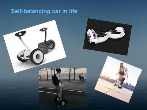
The operation principle of the balance car is mainly based on a basic principle called "Dynamic Stabilization", which uses the gyroscope and acceleration sensor inside the vehicle body to detect the change of the attitude of the car body and utilize the servo control. The system precisely drives the motor to make the appropriate adjustments to maintain the balance of the system.
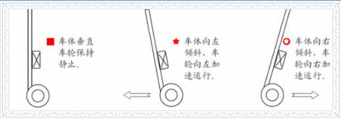
The car has only two wheels on the ground, and the car body will only tilt in the direction in which the wheels roll. Control the rotation of the wheel to offset the tilting tendency of the car body to achieve the car standing.
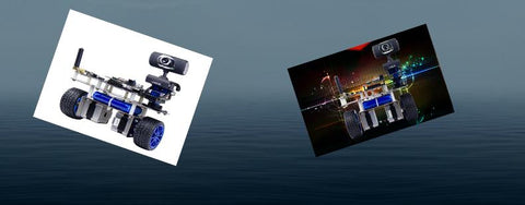
How to make a balance car that belongs to you?
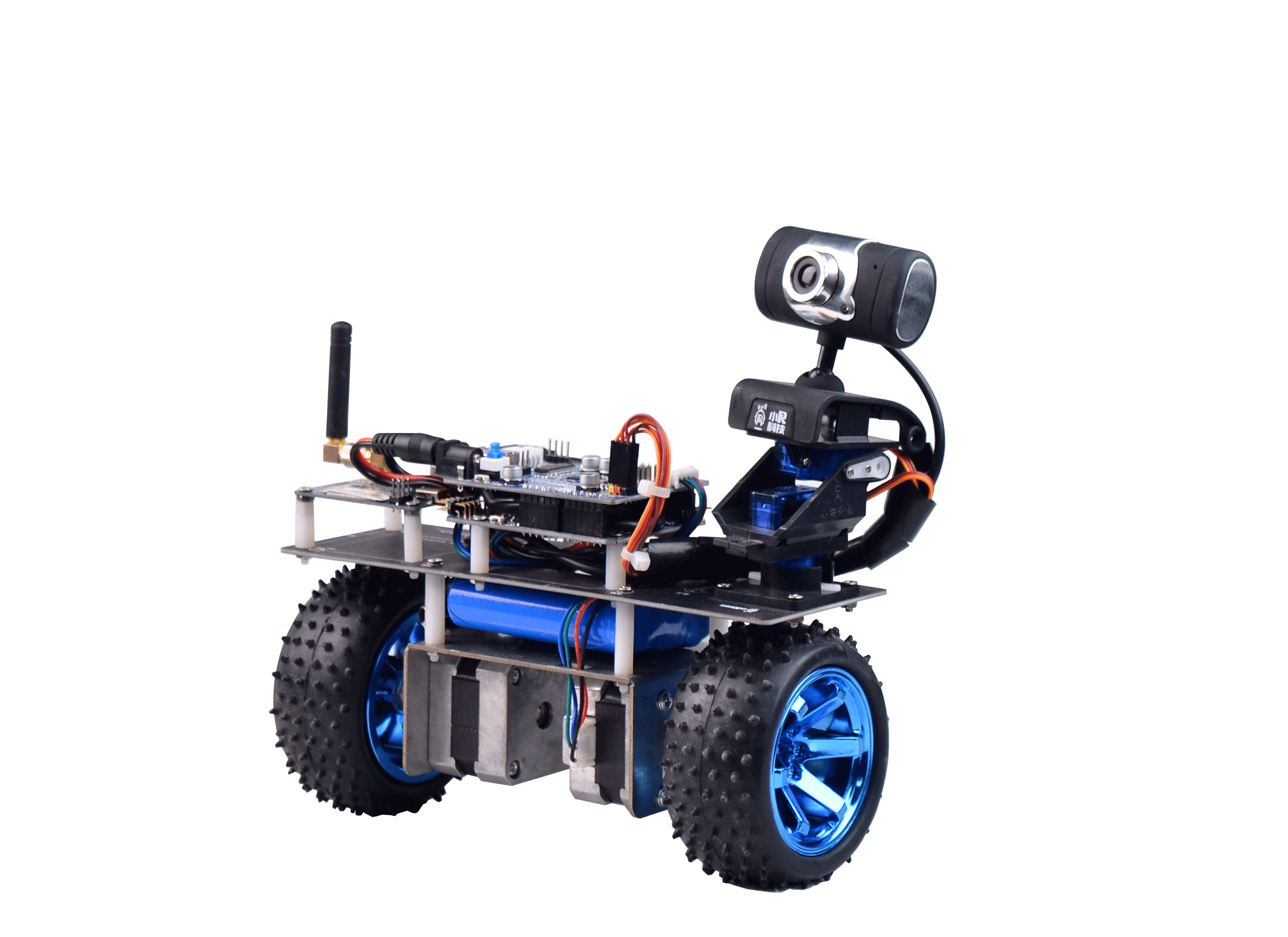
STM32 Self balance WiFi robot car
1、MPU6050 gets the car inclination
2、PID control algorithm
3、Car motor
1.MPU6050 gets the car inclination
(1)MPU6050 attitude sensor
The MPU6050 is a very popular space motion sensor chip that captures the current three acceleration components, three rotational angular velocities, and temperature. Due to its small size, powerful function and high precision, it is not only widely used in industry, but also an artifact of RC enthusiasts. It is installed on various types of aircraft to ride the blue sky.
(2)Read MPU6050 attitude sensor data
The MPU-6050 uses three 16-bit ADCs for the gyroscope and accelerometer, respectively, and quantizes the measured analog to an outputable digital quantity. In order to accurately track fast and slow motion, the sensor's measurement range is user-controllable. The gyroscope's measurable range is ±250, ±500, ±1000, ±2000°/sec (dps), accelerometer measurable range ±2, ±4, ±8, ±16g. We can read the 7 data of MPU6050 through IIC protocol.
(3)MPU6050 data processing
Since the data obtained directly from the MPU6050 is unstable, we need to use some data processing algorithms to get a relatively stable number of data. We need to use complementary filtering algorithm, Kalman filtering algorithm, smoothing filtering algorithm. After processing these algorithms, we can get the trolley inclination we want.
2.PID control algorithm
(1)Why do we need to use PID control algorithm
When the car is standing, it will be dumped due to the influence of the environment. I need to give the wheel a speed to offset the tendency of the car to fall. So how much should this speed be? If the speed is slightly larger, then the car will “rush through” the balance point and will dump to the other side. If the speed is too small, the speed of the wheel will not offset the tendency of the car to fall. In this way, the car can not achieve the goal of standing. We need the speed of the wheels to "just happen" to offset the tendency of the car to fall, so that the car can stand up.
In order to solve this problem, we need to use the PID algorithm to dynamically adjust the wheel speed required to offset the dumping tendency of the car.
(2)PID algorithm understanding
One of the most typical examples of understanding PID control algorithms is the problem of a leaking water tank.
There is a leaking water tank, and the speed of water leakage is not constant. Then we have a bucket, we can control the water in the tank or drown from the tank. In addition we can detect the horizontal plane. Our goal now is to control the horizontal stability on any plane we want.
Note that we need to use the PID in a closed loop system. What is a closed-loop system? There is input and feedback. Input can input a quantity to influence and control our system. Feedback is the state we need to know what we ultimately control. In this leaking water tank system, the input is the bucket. We can add water to the tank through the bucket or drown from the tank to affect the water level of our tank. If we feedback, we must be able to measure the water level. Know what the water level is.
(2)PID algorithm understanding
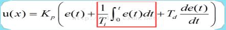
1、 The schematic diagram of the control system is as follows:
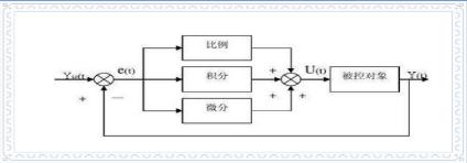
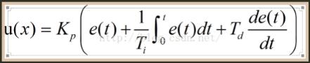
2、Where Kp is the proportional coefficient, Ti is the integral time constant, and Td is the integral time constant.
3、Proportional control understanding
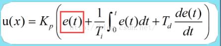
The first is proportional control. Proportional control is like adding water to a tank through a bucket or drowning from a tank. Suppose we need to stabilize the horizontal plane in the A plane, and the actual horizontal plane is in the B plane, then the horizontal plane difference Err=A-B, then the amount of water we need to add to this time is Kp*Err, Kp is our proportional control coefficient. If A>B, Err is positive, add water to the tank; if A<B, Err is negative, drown out of the tank. Then as long as there is a difference between the expected level and the actual level, we will adjust the system by adding water to the bucket.
Some people may have doubts here. If the proportional control coefficient Kp is directly set to 1, then the amount of water added is directly Err=A- B. However, in fact, many systems can't do this. For example, the temperature control system, the actual temperature is 10 degrees, I have to raise the temperature to 40 degrees by heating, can we add 30 degrees to the system at one time? Obviously this is impossible. Then the end result of the proportional control is that the value of Err tends to zero. The formula for the proportional control section is as shown above.
4 、Differential control understanding
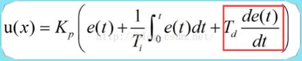
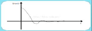
Under the influence of our proportional control, Err starts to decrease (assuming that the horizontal plane A is expected to be larger than the actual horizontal plane B at the beginning, that is, Err is a positive value), that is to say, Err is a slope with time less than 0. Curve, then in the cycle time, Err is larger, the larger the absolute value of the differential, then it will suppress the speed of Err reduction until the final slope is 0 differential. The differential formula is as shown above. Then, with the influence of the differential, the slope of the Err curve eventually tends to zero, as shown in the following figure.
5、Intergral control unerstanding
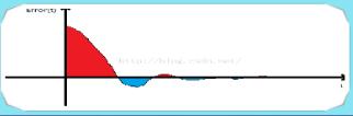
The function of the integral control section is mainly to eliminate the static difference. So how does the integral eliminate the static difference? We know that the integral of the curve is equivalent to the area enclosed by the curve and the x-axis. Proportional control can only adjust Err to 0 as much as possible, but there will be such errors.
The effect of the differential is to stop the slope of the curve to 0, but Err does not necessarily be 0 when the slope is zero. At this time we need points to work. As shown in the figure below, the purpose of the integral action is to make the sum of the area of the red portion and the area of the blue portion 0, so even if the system has stabilized in the proportional control and the differential control portion, there is a static difference as long as Err is not 0. As long as there is a static difference, the integral will have an effect on the system until the system has an Err value of zero. Then our PID control can theoretically achieve a very precise control effect.
3. Car Motor
(1)Stepper motor
Stepper motor is an open-loop control motor that converts electrical pulse signals into angular displacement or line displacement. It is the main actuator in modern digital program control systems and is widely used. In the case of non-overload, the speed and stop position of the motor depend only on the frequency of the pulse signal and the number of pulses, and are not affected by the load change.
When the stepper driver receives a pulse signal, it drives the stepper motor. The set direction is rotated by a fixed angle called the "step angle" whose rotation is performed step by step at a fixed angle. The angular displacement can be controlled by controlling the number of pulses to achieve the purpose of accurate positioning. At the same time, the speed and acceleration of the motor rotation can be controlled by controlling the pulse frequency, thereby achieving the purpose of speed regulation. Compared with the ordinary geared motor, the balance car selects the stepper motor to control accurately and does not need the PID speed control loop.